
Simple Relay Circuit Diagram The design and types of relay switching circuits is huge, but many small electronic projects use transistors and MOSFETs as their main switching device as the transistor can provide fast DC switching (ON-OFF) control of the relay coil from a variety of input sources so here is a small collection of some of the more common ways of switching relays.
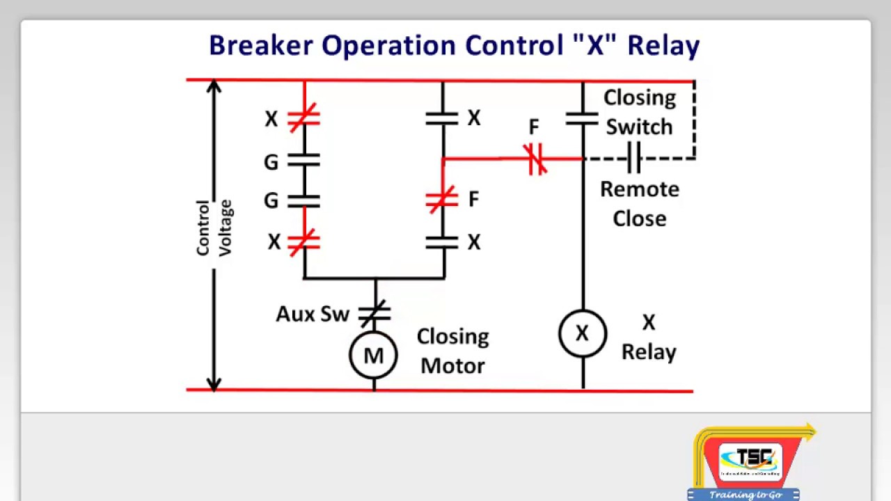
A very common form of schematic diagram showing the interconnection of relays to perform these functions is called a ladder diagram. In a "ladder" diagram, the two poles of the power source are drawn as vertical rails of a ladder, with horizontal "rungs" showing the switch contacts, relay contacts, relay coils, and final control elements (lamps, solenoid coils, motors) drawn in between
Relay Circuit Diagram and Operation
A relay switch circuit is an electrical circuit that uses a relay to control the switching of a load, such as a motor or a lamp, by using a smaller control signal. The circuit consists of several main components that work together to form a functional relay switch system. 1. Relay. The central component of a relay switch circuit is the relay Relay logic basically consists of relays wired up in a particular fashion to perform the desired switching operations. The circuit incorporates relays along with other components such as switches, motors, timers, actuators, contactors etc. The relay logic control works efficiently to perform basic ON/OFF operations by opening or closing the relay contacts but it involves a humongous wiring.
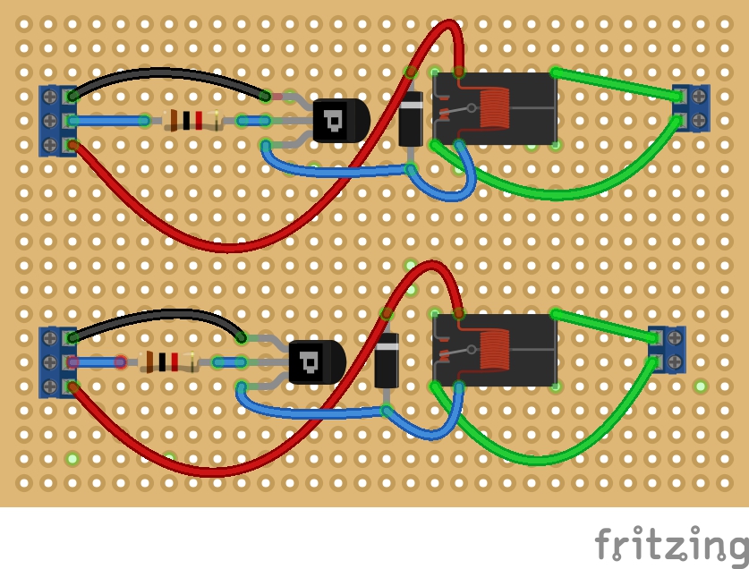
Build a basic relay driver circuit. Single stage low side relay circuit uses one BJT NPN transistor. How to calculate component values. For more information For example, a relay may be controlled by a low-voltage, low-current signal that passes through a delicate switch of some sort (e.g. limit switch, proximity switch, optical sensor), and then the switching contacts of that relay may be used to control a much higher-voltage, higher-current circuit, and even multiple circuits given multiple sets

Introduction to Relay Logic Control Circuit Diagram
The Basics of Control Relays Perhaps the most confusing aspect of relay control circuits for students to grasp is the meaning of normal as it applies to the status of relay contacts. As discussed previously, the word "normal" in this context - whether it be the status of hand switches, process switches, or the switch contacts inside
