Overvoltage protection circuit and method thereof Eureka Circuit Diagram Consider the below image, where we need over-voltage protection for Microcontroller. The microcontroller can be anything that has a maximum rating of 5V across the IO pins. Therefore, more than 5V could damage the microcontroller. The Zener diode used in the above circuit is a 5.1V Zener diode. It will work fine during an over voltage situation.
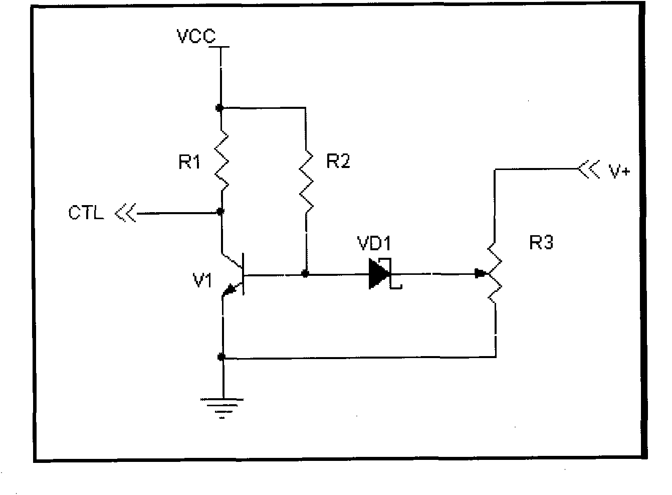
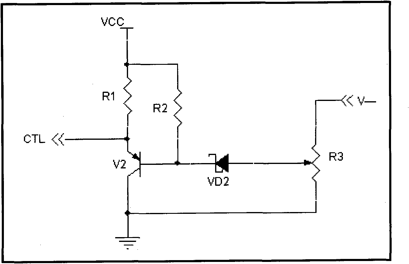
So, we comprehended that both the higher voltages and the lower voltages can do a greater amount of harm to any circuit. Hence, every device needs a voltage protection circuit that can indicate and protect the devices from high or low voltage. Thus, in this tutorial, we are going to Make an "Overvoltage and Under Voltage Protection Circuit" A reference is just a low-current reference, it's not designed to power anything. It could be used as part of a protection circuit or part of an over-voltage detection circuit, or part of a regulated power supply, using a comparator to compare the actual power supply voltage with the reference. If you can't find the exact reference you want you
230V AC Mains Over Voltage Protection Circuit Circuit Diagram
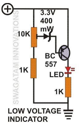
Here simple overvoltage protection circuit is designed by using a Zener diode and transistors. This protection circuit acts as a voltage regulator and also a circuit breaker. you can choose the Zener diode voltage range depending on your load or device voltage range, we have a 5V load and hence we have used a 5.1V Zener diode. To solve this problem, we are going to build an over voltage protection device with an op-amp, which can detect high voltages and can cut of the input power in a fraction of a second protecting the device from a high voltage surge. Also, there will be a detailed test of the circuit to verify our design and working of the circuit.
An automatic voltage regulator circuit is a handy electronic device that ensures a steady and optimum voltage supply, protecting the devices from damage caused by under or overvoltage scenarios. In this article, we will guide you through the process of building your own automatic voltage regulator circuit, complete with a detailed diagram.

Voltage Protection Circuit ... Circuit Diagram
In some situations where the input voltage is higher than expected, we always use an overvoltage protection or crowbar protection circuit. The crowbar protection circuit is one of the most used overvoltage protection circuits. A power supply can fail in many ways; similarly, there can be many ways to protect a circuit from overvoltage.